Quality of Service (QoS) - Voice, Video, Data Traffic

Where we need Quality-of-Service(QoS) in a Network?

Ans: In Converged Architecture/Unified Communication network where Voice/Video/Data services are implemented.

Converged Architecture 

Converged Architecture - Combination of Multiple Services

Data:

Data Service is an Best Effort Services and it is Insensitive. It using CRC for data integrity check i.e. ACK, REQ, SYN, FIN etc.

Voice and Video:

Real time services, **remember - stored voice & video in computer is data. 
Most important thing for Voice and Video is Quality-of-Experience (QoE) which depends upon three things:
  • Delay (Latency)
  • Jitter (Inconsistent Delay)
  • Drops

Voice

  • Real time service, IP phone, analog is converted into digital form or packet form.
  • Voice Packets are small (8 Kbytes - 64 kbytes)
  • Voice Concealment Program is used
  • Drop are allowed in Voice, 1 drop in 10000 voice packets (more than this is not very good QoS)
  • Delay is not allowed in Voice, so called Delay Sensitive Communication/Low Latency communication.

Video

  • Real time service, High definition (8.5 mb) and Standard Definition (2.5 mb)
  • Packets are in form of frames.
  • Need Consistency of Video frames
  • Frames - I (Index), B (Actual Video) , P (Padding) - Blank screen means I frame is dropped, Glitch means B frame is dropped.
  • Drop are not allowed in video, so called as Drop Sensitive Communication. 1 drop in 100000 video packets not more otherwise is not good.
  • Delay is allowed, up to 200ms. 

*******IMPORTANT********
If there is a device with input DATA-700 MB, VOICE-64 kb, VIDEO-8 MB and device having 5 MB BW Output, so which packet will go first, then second and last?


ANS: 
  1. VOICE because Delay not allowed.
  2. VIDEO because Delay is allowed and data goes first then video will go into buffering and if it overload it will drop.
  3. DATA because it is insensitive so last.
For this, devices should be capable of Classifying and Prioritization the packet which is called as QoS.
********IMPORTANT********* 


Configuration:

Coming up....

[http://www.cisco.com/c/en/us/support/docs/switches/catalyst-3750-series-switches/91862-cat3750-qos-config.html

&

http://www.cisco.com/c/en/us/td/docs/ios/solutions_docs/qos_solutions/QoSVoIP/QoSVoIP.html]


★CT21

Reference: https://rstforum.net/ (CCNA training)

Three Tier Architecture - Network Design


Three Tier Architecture (Networking) or Hierarchical LAN Network Model


  • Access Layer
  • Distribution Layer
  • Core/Backbone Layer


Fig:1

Access Layer: (Switches/L2)

Provides work-group/users access to the network. Features includes:
  • Highly Available
  • Broadcast suppression
  • Fully Redundant
  • Highly Scalable
  • No Single point of failure (NSPOF)
Functions:
  • Access Capability (Connectivity)
  • Port Security
  • VLAN creation
  • L2 access security
  • Spanning tree

Distribution Layer:(Routers/Switches/L3) 

Most important layer is Distribution because maximum traffic management will happen in the same building so maximum work load on Distribution Layer.

Provides policy based connectivity and controls the boundary. Features & Functions includes:
  • Maximum Traffic Manipulation - Manage & Handling traffic
  • Route and VLAN aggregation
  • Inter-VLAN routing
  • Filtering and Security (ACL)
  • Trunk termination
  • Redundancy and Load Balancing
  • QoS 

Core Layer: (All to All Connectivity)

Provides Fast Transport. Features & Functions includes:

  • Fast (High Speed) Switching
  • L2 Transport only
  • No Traffic Manipulation
  • High Reliability
  • Fault Tolerance
  • QoS

Process:

Very Important: Bring as much L3 switching/Routing as possible to control broadcast and void VLAN in your design because VLAN is use for security, separation and management.

Following diagram describe High Available, Secure, Better QoS and Highly Scalable design.   


Fig:2


★CT21
Reference: https://rstforum.net/ (CCNP training) | Cisco Networking Academy | CCDA 200-310

Address Resolution Protocol (ARP) Poisoning and Analyzing with Wireshark.

Prerequisites: Knowledge on ARP process. [http://www.erg.abdn.ac.uk/users/gorry/course/inet-pages/arp.html]

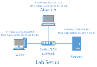
Lab Setup for ARP Poisoning


In this lab we are assuming that the Attacker is compromised the network, so its in same LAN segment.

Normal ARP between User and Server will have ARP cache (table) as below:
  • User PC
  • Server  


Now the attacker does a ARP Poisoning in the network, now the ARP tables changes as below:

  • User PC
  • Server


ARP Poisoning: Server and User will be communicating with the attacker PC even though they think they are communicating with each other. This kind of attack can be easily be detected with the help of Packet Analyzer or checking the ARP table.

Wireshark Analysis on ARP Poisoning


When apply ICMP, we get the response from the destination but the path is via Attacker PC. As you can see the wireshark packet capture, packet from User is going Attacker then its going to destination and via versa.
Also, Attacker learns the layer 2 information on the LAN segment and changes the ARP table.

[ For more details -  http://www.cisco.com/c/en/us/products/collateral/switches/catalyst-6500-series-switches/white_paper_c11_603839.html ]


★CT21