Quality of Service (QoS) - Voice, Video, Data Traffic

Where we need Quality-of-Service(QoS) in a Network?

Ans: In Converged Architecture/Unified Communication network where Voice/Video/Data services are implemented.

Converged Architecture 

Converged Architecture - Combination of Multiple Services

Data:

Data Service is an Best Effort Services and it is Insensitive. It using CRC for data integrity check i.e. ACK, REQ, SYN, FIN etc.

Voice and Video:

Real time services, **remember - stored voice & video in computer is data. 
Most important thing for Voice and Video is Quality-of-Experience (QoE) which depends upon three things:
  • Delay (Latency)
  • Jitter (Inconsistent Delay)
  • Drops

Voice

  • Real time service, IP phone, analog is converted into digital form or packet form.
  • Voice Packets are small (8 Kbytes - 64 kbytes)
  • Voice Concealment Program is used
  • Drop are allowed in Voice, 1 drop in 10000 voice packets (more than this is not very good QoS)
  • Delay is not allowed in Voice, so called Delay Sensitive Communication/Low Latency communication.

Video

  • Real time service, High definition (8.5 mb) and Standard Definition (2.5 mb)
  • Packets are in form of frames.
  • Need Consistency of Video frames
  • Frames - I (Index), B (Actual Video) , P (Padding) - Blank screen means I frame is dropped, Glitch means B frame is dropped.
  • Drop are not allowed in video, so called as Drop Sensitive Communication. 1 drop in 100000 video packets not more otherwise is not good.
  • Delay is allowed, up to 200ms. 

*******IMPORTANT********
If there is a device with input DATA-700 MB, VOICE-64 kb, VIDEO-8 MB and device having 5 MB BW Output, so which packet will go first, then second and last?


ANS: 
  1. VOICE because Delay not allowed.
  2. VIDEO because Delay is allowed and data goes first then video will go into buffering and if it overload it will drop.
  3. DATA because it is insensitive so last.
For this, devices should be capable of Classifying and Prioritization the packet which is called as QoS.
********IMPORTANT********* 


Configuration:

Coming up....

[http://www.cisco.com/c/en/us/support/docs/switches/catalyst-3750-series-switches/91862-cat3750-qos-config.html

&

http://www.cisco.com/c/en/us/td/docs/ios/solutions_docs/qos_solutions/QoSVoIP/QoSVoIP.html]


★CT21

Reference: https://rstforum.net/ (CCNA training)

Three Tier Architecture - Network Design


Three Tier Architecture (Networking) or Hierarchical LAN Network Model


  • Access Layer
  • Distribution Layer
  • Core/Backbone Layer


Fig:1

Access Layer: (Switches/L2)

Provides work-group/users access to the network. Features includes:
  • Highly Available
  • Broadcast suppression
  • Fully Redundant
  • Highly Scalable
  • No Single point of failure (NSPOF)
Functions:
  • Access Capability (Connectivity)
  • Port Security
  • VLAN creation
  • L2 access security
  • Spanning tree

Distribution Layer:(Routers/Switches/L3) 

Most important layer is Distribution because maximum traffic management will happen in the same building so maximum work load on Distribution Layer.

Provides policy based connectivity and controls the boundary. Features & Functions includes:
  • Maximum Traffic Manipulation - Manage & Handling traffic
  • Route and VLAN aggregation
  • Inter-VLAN routing
  • Filtering and Security (ACL)
  • Trunk termination
  • Redundancy and Load Balancing
  • QoS 

Core Layer: (All to All Connectivity)

Provides Fast Transport. Features & Functions includes:

  • Fast (High Speed) Switching
  • L2 Transport only
  • No Traffic Manipulation
  • High Reliability
  • Fault Tolerance
  • QoS

Process:

Very Important: Bring as much L3 switching/Routing as possible to control broadcast and void VLAN in your design because VLAN is use for security, separation and management.

Following diagram describe High Available, Secure, Better QoS and Highly Scalable design.   


Fig:2


★CT21
Reference: https://rstforum.net/ (CCNP training) | Cisco Networking Academy | CCDA 200-310

Address Resolution Protocol (ARP) Poisoning and Analyzing with Wireshark.

Prerequisites: Knowledge on ARP process. [http://www.erg.abdn.ac.uk/users/gorry/course/inet-pages/arp.html]

Lab Setup for ARP Poisoning


In this lab we are assuming that the Attacker is compromised the network, so its in same LAN segment.

Normal ARP between User and Server will have ARP cache (table) as below:
  • User PC
  • Server  


Now the attacker does a ARP Poisoning in the network, now the ARP tables changes as below:

  • User PC
  • Server


ARP Poisoning: Server and User will be communicating with the attacker PC even though they think they are communicating with each other. This kind of attack can be easily be detected with the help of Packet Analyzer or checking the ARP table.

Wireshark Analysis on ARP Poisoning


When apply ICMP, we get the response from the destination but the path is via Attacker PC. As you can see the wireshark packet capture, packet from User is going Attacker then its going to destination and via versa.
Also, Attacker learns the layer 2 information on the LAN segment and changes the ARP table.

[ For more details -  http://www.cisco.com/c/en/us/products/collateral/switches/catalyst-6500-series-switches/white_paper_c11_603839.html ]


★CT21


Private VLAN


Private VLAN Architecture Explanation:


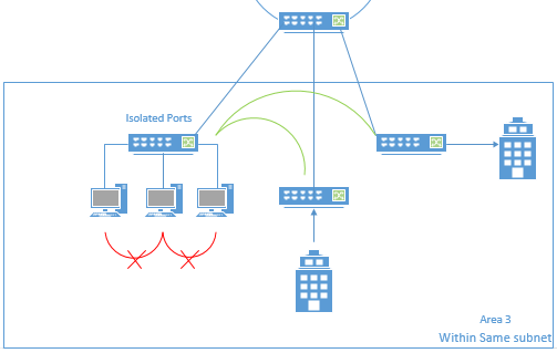
Service Provider has Ring topology in different area to give connection to internet to there customers, as shown in above diagram. Its a fiber ring connected to aggregation switch to pass the traffic of the customer to internet and before going to internet they also implement Broadband Policy Management (BPM) to control the bandwidth of the customer as per there plans purchased. 

From the diagram, ring is connected to three areas but focusing on area 3 only. 

Why we need Private VLANs?  
  • In area 3, all building will be in same subnet IP provided by service provider so only one customer can take a connection to internet and others can share with him or customer ask oters to pay him instead of SP as they are in same subnet. Most importantly, security is weak.
  • To increase the security, we have to divide into more VLAN (subnets) so that they can not communicate with each other but making more subnets will be wastage of IPs, more SVI on switches, more processing and CPU cycling. For every home different subnet, huge and complex task for service providers.
  • Best solution to this problem is PRIVATE VLANs. Ports cannot communicate with same subnet when private vlan is applied.

PRIVATE VLANs:

Types:
  1. Promiscuous
  2. Isolated
  3. Community 
For more details refer: http://www.cisco.com/c/en/us/td/docs/switches/datacenter/nexus5000/sw/configuration/guide/cli/CLIConfigurationGuide/PrivateVLANs.pdf

Communication between Private VLAN types
Option 1: Only Isolated ports

Private VLAN - Isolated port
Service provider puts the switch ports in isolated host so now users in the same building cannot communicate to each other but can communicate to other buildings with the same isolated ports. So, to enhance the security they introduce promiscuous type.

***Isolation is local to a switch means isolated port vlan cannot communicate with isolated port vlan on the same switch but it can communicate with other switch with same isolated port vlan. 

If isolation is local to switch then we can put each building in different isolation vlans but it will make more complex because more users, more SVI on switches. Hence, not a better solution.

Option 2: Isolated and Promiscuous ports


Promiscuous port associated with Isolated port 
Locally switch ports are isolated but outbound traffic will convert it to promiscuous vlan, so two vlans will be configured primary vlan for isolation which will be associated with secondary vlan for promiscuous which acts as a gateway for the local switch.

Now, security is also enhance and user are divided within same subnet with Private VLANs to connect to Internet. Service Provider is also happy and can give connection as per user requirements.

Option 3: Community and Promiscuous ports

Only differences is few users will be in same community so that they can communicate within the same building but outbound will be promiscuous port to connect to internet.


★CT21
Reference: https://rstforum.net/ (CCNP training)

VPN - IPSec

IPsec Process & Implementation


IPSec Process:

The most important protocol used by IPsec-VPN is Internet Key Exchange (IKE) protocol. It is use for negotiation and establishment of secure site-to-site or remote access VPN tunnels.

IKE version 2 (IKEv2) is used.

To have successfully IPsec tunnel, two IKE phases could be completed successfully.

IKE Phase I - Management Tunnel
  • This phase mainly focus on negotiations and authentication.
  • Protect management traffic, not users packets.
  • Keepalive packets are used.
  • Successful negotiation of phase is possible only if both ends have same Hash algorithm, Encryption algorithm, Diffie-Hellman (DH) group, Authentication method and Lifetime. This is also called as IKE phase 1 policies.

IKE Phase II - IPsec Tunnel
  • Users packets are encrypted across untrusted networks between the VPN peers. 
  • Hashing and encryption algorithm is used to protect the user's packet, also called IKE Phase 2 policy.
  • Using to modes - Tunnel mode and Transport mode [ For better understanding - http://www.firewall.cx/networking-topics/protocols/870-ipsec-modes.html ] 
IPSec Implementation:


Figure 1 


Firewall to Firewall & Router to Router VPN configuration is slightly different. Using Cisco Packet Tracer

As per the Figure 1, configuration is between HQ -- Branch 1 with Firewall.

IKE Phase I Configuration: (both peers should have same policy)

!
crypto ikev1 policy 1             //policies to match with the peers
encr aes                                  //Encryption aglorithm
hash md5                               //Hash aglorithm
authentication pre-share        // Authentication method
group 5                                  // Diffie-Hellman (DH) group
lifetime 3600                         //Lifetime

!
object network Branch1_network
subnet 192.168.2.0 255.255.255.0
object network HQ_network
subnet 192.168.1.0 255.255.255.0
!
access-list out_crypto extended permit  object HQ_network object Branch1_network
!
tunnel-group 200.200.200.2 type ipsec-l2l
tunnel-group 200.200.200.2 ipsec-attributes         //key for authentication
ikev1 pre-shared-key 12345

!

Negotiation between HQ -- Branch 1


Phase I - Establishment


[ More information on Phase I states - https://www.tunnelsup.com/isakmp-ike-phase-1-status-messages/ ]

IKE Phase II Configuration:

!
crypto ipsec ikev1 transform-set HQ esp-aes 256 esp-sha-hmac
!
crypto map out_map 1 match address out_crypto       //access-list
crypto map out_map 1 set peer 200.200.200.2            //peer ip address
crypto map out_map 1 set ikev1 transform-set HQ     // ipsec
crypto map out_map interface outside                         //interface applied
crypto ikev1 enable outside
!

Phase II state


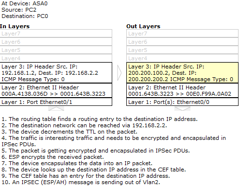
Inbound & Outbound packet


Outbound packet details


IPSEC Information


Returning Packet


Download configuration & .pkt file: 


 ★CT21
Reference: CCNA Security 210-260 Official Cert Guide

Subnetting Extra (Tips & Hints)

I. Bit to mask: (Magic Box fro Subnetting)

Bit to Mask Table

It is easy to write subnet mask in /8, /16...
What if you have to write in bit format or decimal format?
For that you have to just remember this Magic box (Bit to Mask Table).

So, we know:

/8 = 255.0.0.0
/16 = 255.255.0.0
/24 = 255.255.255.0
/32 = 255.255.255.255

What if we have /10, /27, /14...?

Using Magic Box,

/10 = /8 + /2 = 255.192.0.0 (2 is the number on the first row and take the value from below)
/27 = /24 + /3 = 255.255.255.224
/14 = /8 + /6 = 255.252.0.0
/21 = /16 + /5 = 255.255.248.0

soon on..

**Count from Left

For Wildmask just inverse the subnet mask

/27 = 0.0.0.31
/21 = 0.0.7.255

and soon on...


II. Host requirement are more

Example: 16.20.0.0/16, requirement 1000 hosts.

According to the host view of point subnetting,

  • 1000+2 = 1002
  • 2^10 = 1024, 10 bits on host side and 1024 numbers of host.
  • 32-10 = 22 bits on network side
  • 16.20.0.0/22
Now how you will divide into blocks, 
  • 1024/256 = 4, 256 (0 -255) is possible so we need 4 block of 256 (4X256)
Block 1: 16.20.0.0 - 16.20.3.255 /22
Block 2: 16.20.4.0 - 16.20.7.255 /22
.
.
.
.
Block last: 16.20.252.0 - 16.20.255.255 /22


★CT21
Reference: https://rstforum.net/ (CCNA training)

How to do Subnetting?


Easy way to do SUBNETTING

Example:

If you want to design your network and connect HQ and Branches using one IP block, so we need subnetting.
Below diagram will help in understanding Subnetting.


IP address has NETWORK side and HOST side  **IP addressing.

**SUBNET MASK always says bit on network side.

So, Subnetting can be done by 2 ways:
  1. Host Side subnetting
  2. Network Side subnetting
I. HOST SIDE SUBNETTING:

If we want to design host point of view, collect all the number of host in your network according to the branches and connectivity.

Branch1 = 12 Host;
Branch2 = 24 Host;
Branch3 = 28 Host;
Branch4 = 30 Host;
Connectivity = 2 Hosts;
Process:
  • Identify which branch has more requirement (Branch4) because if you break network according to the branches, Branch4 will have shortage of IP's.
    • Branch4 = 30 hosts 
  • Add 2 more hosts (30+2=32) because as you know a block of IP addresses contains a Network address and Broadcast address so it cannot be use as host address.
  • Now match nearest 2^n to the value 
    • 2^5=32, n=5
      • 'n' means number of bit on host side. 5 bits on host side.
      • 32 means total number of host.
  • IP address has total 32 bits and we have taken 5 bits for host side. So, 32-5=27, 27 bits on network side.
    • 16.20.20.0/27
  • We have successfully done subnetting from /24 to /27, 3 bits we have taken from the network side which will be used for our subnet blocks.
  • Now you can use this blocks to each of your branches and connectivity, each block are in same subnet (can be switched).
  • Remember First address is Network address (16.20.20.0) and Last address is Broadcast address (16.20.20.31) they cannot be use for hosts.
    • If you want to use them use cmd:
      • IP subnet-zero
  • This method is Fixed Length Subnet Mask (FLSM).
  • Disadvantage is many IP's will be wasted or unused in your network. We used VLSM - Variable Length Subnet Mask. 
II. NETWORK SIDE SUBNETTING:

If we want to design network point of view subnetting, collect number of networks needed


Process:
  • We need 8 n/w's. Don't need to add 2 more to the n/w as we did in host process.
  • Nearest 2^n to the number of networks required; 8=2^3
    • Where 'n' means number of bits to take from network side. 3 bits we have to take from network side.
  • As per our example, 24 bits are there in network side so we have to take 3 bits more.
    • 24+3=27 bits on network side
  • Total bits are 32 bits in IP address
    • 32-27=5, 5 bits on host side
    • 2^5= 32 (Similarly to Host point of view); 32 number of hosts.
  • We have successfully done subnetting.

III. VSLM:

Since, there are to many wasted or unused IP addressing in FLSM we use VSLM to overcome this disadvantage in FLSM.

\
  • We need 2 hosts on all the connectivity between HQ and Branches, so we will apply Host point of view process and you will obtain,
    • 16.20.20.0/30
  • Do it from each links,
    • 16.20.20.4/30; 16.20.20.8/30; 16.20.20.12/30
  • Similarly, for each branches according to the host and add to the above block to continue your IP subnetting.
    • Branch1 = 16.20.20.16/28
    • Branch2 = 16.20.20.32/27
    • Branch3 = 16.20.20.64/27
    • Branch4 = 16.20.20.95/27
  • So, if you notice we have saved lots of IP's that can be used if we want to extend the network (adding another branch office).
  • Finally, Subnetting design for our example as follows:


★CT21
Reference: https://rstforum.net/ (CCNA training)